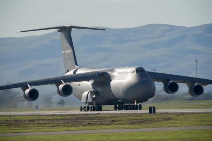
• Aircraft Wing Structure

    In aeronautics Wing are airfoils attached to each side of the fuselage, So the design of the wing depends on many facts like lift to weight ratio, rate of climb, size, weight and which aircraft it is used,

  • AirCraft Fuselage Structure

    Fuselage is a body of an aircraft to which the wings, tail and Landing Gear units are attached. Design and size of the fuselage varies according to the function to the aircraft. The word fuselage comes from a French word “fusele” means “splindle-shape”

  • Landing Gear

    Landing gear is an undercarriage part of the flight landing system. Aircraft landing gear has wheels equipped with shock absorbers on light planes and Hydraulic or pneumatic oleo struts on larger aircraft.

Wednesday, July 22, 2020

Control Surface of airplane


Control Surface of airplane

              Control surface of Aircraft is an aerodynamic device mean by which pilot stabilize aircraft and controls the direction and altitude of an aircraft on flight. Control surface is a movable surface which is lighter in construction has light  spar rod at the front edges to provide strength and rigidity, the spar connect the ribs and covered by the thin skinned sheet. The tabs are attached to the trailing edge of the control surface additional device will be attached based of purpose the control surface is used for transmission of tab loads to the surface.


Sheet Materials used in Control Surface
  1. Metal structure                   -        Covered with metal skin
  2. Composite Structure          -        Covered with fabric
  3. Wooden Structure              -        Covered with Plywood or fabric

Drilling

The hole on the surface made using drain holes to prevent water  trapped inside the structure , which causes the control surface to be thrown out of balance

Jointing

Process involved in jointing the components includes fasteners like adhesive and bonding agents.

Flight Control Surface are sub branched into

  • Primary Control Surface
  • Secondary Control Surface

Primary Control Surface is designed to provide adequate response to controlling device giving a natural feel.
At low speed control will be smooth and sluggish
At high speed control will become increasingly firm

Responding to speed
At low speed the aircraft respond slow to control applied
At high speed the aircraft respond more rapid (faster) to control applied

Primary Control Surface includes:

Ailerons - (ROLL) Control motion along longitudinal axis.

Elevator - (PITCH) Control rotational motion along lateral axis.

Rudder  - (YAW) Control motion along Vertical axis.


Secondary Control Surface are use to improve the aircraft performance characteristics and to release the excessive control loads applied.


Secondary Control Surface includes:

Wing flaps - Used to increase the Lift and Drag increase while Take off.

Slats - Located on the leading edge of the wings. Creates enough lift at high Angle of attack.

Slots - Span wise gap present at each wing allowing air to flow between the wings, which creates lift thus reduces stall.

Trim tabs - Connect trailing edge to large Control Surface, Used to Stabilize the aircraft.

Balance tabs - Control loads on the control surface is significantly reduced, makes aircraft easy to fly.

Anti-Balance tabs - Maintain the stability in the desire position.

Servo tabs - Small Hinged device to assist the movement of the control surface.


The Combination of this Control Surface of Aircraft helps the pilot in controlling and stressing the aircraft during flight .


Sunday, July 12, 2020

Aircraft Wing Structure

Aircraft Wing Structure

          The Wing, in aeronautics are airfoils attached to each side of the fuselage Wings is the primary lifting surface of the aircraft that support the aircraft in flight, The load acting on the aircraft structure are carried the wing structure. So the design of the wing depends on many facts like lift to weight ratio, rate of climb, size, weight and which aircraft it is used, thought its shape may be widely varied its function remains the same.

Aircraft Wing Structure


Basic features of Wing Constructions

The primary structural parts of the wing are spars, ribs, and stringers.


Spars are also called as wing beams is a main member of the wing structure, it extends from the fuselage to the tip of the wing, all the forces and loads acting on wing are carried and balances by the spars. When the engine or landing gear are mounted on the wing , Spare incorporate structure attached to the components, as spars are designed to have greater bending stress.

Ribs are also called as plain ribs, it’s a chord wise member of the wing structure used to give wing structure it shape, It extends from the leading edge to the trailing edge of the wing It transmits air load from skin to the spars also stabilize the spare against twisting

Stringers are assist to hold shape of wing the span wise called stringers are used. They are attached to the skin usually found fare closed spaced on the upper wing surface, it is used on compression and stiffening of the compression skin to overcome the induced bending loads. But when the wing need of more stiffening where skin is reinforced by panels instead of individual stringers.


Based in this concept, Wing lift the aircraft on air and keeps flying.


For more Related Topic and Information on Aircraft Technology - CLICK HERE


Saturday, July 11, 2020

Types of Aircraft Fuselage Structure

Types of Aircraft Fuselage

            The basics of the Aircraft Fuselage was explained in the before posts (https://sabaeroline.blogspot.com/2020/07/aircraft-fuselage-structure.html), Fuselage types would clearly explain in the present post.


Aircraft Fuselage


    In general, fuselage is classified into three major types base on the method by which stress are transmitted to the structure.

There are three most common types of fuselage are:

Truss or Frame Type Fuselage


A truss is a light gauge steel tube assemblage of members forming a frame triangular shape which giver geometric structure to the fuselage. The Primary members of Truss are the four logerons, the longerons are longitudinal member of the fuselage. Lateral bracing are placed at intervals between the longerons. The lateral surface are called as Bulkheads, Space between two bulkheads are called as bays. Lateral and Longitudinal member are made strong stell wires which are design to withstand compression during load applied.

Truss Fuselage are sub-branched into

  • Pratt Truss
  • Warren Truss

Monocoqne Structure


The word Monocoqne is French word which means “single shell”. In this type the fuselage skin carries all structural stress. The design involves constructing a tube or core which involves no internal structural members which looks like a empty Shell. These types of fuselage are formed by riveting preformed two half together. This Structure carry load effective when the diameter is small. Increasing of the structure diameter depends on the internal cavity.

Semi Monocoqne Structure


It is combination of Truss and Monocoqne type structure together. In Present days Aircraft become large Monocoqne structure not to strong enough. Weight to strength ration is ineffective. Longerons are run length across the monocoqne structure jointing the frame together. Now the Longerons and frame is attached the thin alloy skin shell by rivets and abrasive bonding.

Semi Monocoqne Structure type of fuselage is commonly used both military and commercial aircraft in Modern Days.


For more Related Topic and Information on Aircraft Technology - CLICK HERE


Thursday, July 9, 2020

AirCraft Fuselage Structure

Fuselage of Aircraft

    Fuselage is a body of an aircraft to which the wings, tail and Landing Gear units are attached. Spaces from the cockpit cabin, Passenger cabin, Cargo, Controls unit are located inside the fuselage. Design and size of the fuselage varies according to the function to the aircraft. The word fuselage comes from a French word “fusele” means “splindle-shape” Fuselage is a long and vertical spindle hollow tube. The hollow shape design provides maximum strength with minimum weight.


Fuselage are designed to satisfy two major criteria:

  • Protect the passengers in the event of crash.
  • Efficient in fitting together the wing, tail, landing gear and other control surface in perfect place accomplished with interior space for passenger comfort with minimum frontal area to contour drag for maximum performance.

Fuse large must have a point of attachment for each part such as wings, tail, Landing Gear and Engines to arrange and installed. So that at time of emergency this part can be inspected, removed, repaired and replaced again easily. The fuselage must be very strong at the point of attachment as more loads would be acting on the fuselage and fitted parts during flying and landing.

Outer Design Criteria of Fuselage

Outer Design Criteria of Fuselage

Fuselage is the outer shell of the aircraft, the cabin inside are fully pressurized and the pressure inside the aircraft is greater than the pressure outside due to which the fuselage is exposed to different stress, It must be designed with strong durable material. If were any pressure loss occurs. Oxygen levels will drop it can create a dangerous environment to the crew and the passenger inside.

During the time of rotation of the aircraft more torque will be produce fuselage should be designed to withstand this torque force which leads to collapse of the entire structure, as more load will be acting on the outer surface of Fuse large.

Fuselage design base on Aircraft Usage

In fighter jet have a slender and streamline fuselage  to contour drag for maximum performance  and cockpit will only cabin space present large enough only for the controls and pilot. Cockpit is place on the top of the fuselage for ground visualization and the engines and fuel are place at the rear of the fuselage.


fighter jet Fuselage Sructure

In airlines Civil aircraft use to have a wide, long fuselage carry the many number of passenger as well as cargo. The cockpit will have large space and separate desk for passenger cabin and cargo, Cargo space will be located below the passenger cabin and fuel is stored at the wing.

airlines Civil aircraft Structure


In single engine aircraft the engine is mounted in nose of the fuselage. Cockpit will be place at the top to provide ground visibility.

single engine aircraft Structure

Fuselage skeleton and skin

Fuselage shielded by a thin sheet of material stiffened by large number of longitudinal stringers running together with transverse frames place between, they carry bending moment, shear force and torsional load which causes axial stresses in the stringers and skin. As shear stress acts on the skin because of the resistance stringers the shear force gets ignored.

Fuselage skeleton and skin

(Shear Force: Force acting perpendicular to its longitudinal axis)

Distance between adjacent stringer is usually small due which shear flow in the connecting panel is small.

Fuselage skeleton and skin2
Fuselage skeleton and skin


Material Used

Most airplane uses an Aluminium Fuselage, As Aluminium is strong, corrosive resist to rust and light weight. This characters makes aluminium effect used material for making aircraft component which includes fuselage.


For more Related Topic and Information on Aircraft Technology - CLICK HERE


Tuesday, June 30, 2020

TYPES OF LANDING GEAR


TYPES OF LANDING GEAR

        The basics of the landing gear was explained in the before posts.(https://sabaeroline.blogspot.com/2020/06/aircraft-landing-gear.html) Landing gear types would clearly explain in the present post. As pilot tries, Not Every Aircraft landing is perfect due to Bad weather conditions, short landing etc., Landing gear play important role at time of rough landing, handles the aircraft smoothly and safely landing without breaking or collapsing the aircraft into pieces. 


TYPES OF LANDING GEAR

There are many types of Landing gear. The types of landing gear used in the aircraft depend on two things design of the aircraft (like military, civil purpose) and its intended use (like Cargo, commercial).There are three main types of landing gears used.

Tail wheel Landing Gear
Tail wheel Landing Gear is also known as Conventional or traditional type landing gear because this was milestone for majority of the aviation history, used in the other legendary fighters of WW2. The main gear are located forward to centre of gravity of flight, which makes the tail to get support  from the third wheel assembled in the tail of the aircraft. In some aircraft skid replaces the third wheel which helps slow the aircraft while landing and provide direction stability in earlier aircraft.


Tail wheel Landing Gear

By raising the angle of fuse large when fitted with conventional gear allows to fix long propeller in front of engine for older aircraft, It also provide increase ground clearance of the forward fuse large with is also a advantage in using Conventional Landing Gear.

Directional stability is controlled by different breaking system until the aircraft speed comes under the control of the Rudder. Steerable tail wheel connected to the rudder and rudder pedals by cables. For smooth and easy landing springs fixed for damping.

Tandem landing gear
Most of the aircraft using tandem landing gear are military planes and spy planes. This type of landing gear has a main gear and tail gear aligned on the longitudinal axis of the aircraft. 

Tandem landing gear


The main advantage of Tandem landing gear design reduces drag when deployed they are retractable.

Tricycle-type landing gear
The most common type landing arrangement used in modern aircraft is the Tricycle-type landing gear consist of a nose gear and main gear. Larger and small aircraft today used this gear arrangement.

Tricycle-type landing gear

Benefits
  • Allows more forceful application of the breaks without noise created over when Breaking which increases high landing speed.
  • Provides better visibility from the flight while landing and ground maneuvering.
  • Weights are equally spread over large area and are equally distributer each Gears provide a better safety margin.
  • Aircraft centre of gravity lies forward of the main gear, force act on CG point makes the aircraft moving forward avoiding looping which prevents groung-looping.
Landing Gear Design
Depend on the Aircraft usage and operation the landing been designed either Fixed Gear (immovable) Retractable Gear (movable).


Monday, June 29, 2020

Fuel System


Fuel System

          
Fuel system in aircraft is designed to deliver uniform flow of clean fuel from the tank to the propulsion system of the aircraft without any interruption to power system during continuous flight at high altitude, during all approved maneuvers.  Each fuel tank is equipped with internal fuel pumps, valves and plumbing to feed fuel to the engine to produce thrust.
Air Craft Fuel System

          Fuel system consist multiple fuel tanks located in the wing or fuselage base on aircraft design, intended use and as well as age aircraft determine which fuel tank to be installed. The tanks are made of non corrosive materials that are non reactive aviation fuel. Aluminium alloy are more commonly used in modern aircraft fuel tank of its light weight and corrosive resistant, Synthetic rubber coated type fuel cells are also used.

                     Fuel System parts


        In high wing aircraft there is no need of any pumps to feed the fuel. Gravity propels the fuel from tank to the engine. In lighter Aircraft and low wing aircraft fuel tanks are located inside the wing. Have filler opening at the top of the wing through which fuel can be filled and drains in the bottom by which any moisture can be removed, to drain fuel sample for inspection. Electrical Pump been used to pass the fuel from the tank to the Carburetor, and pressure gauge will be attached to the pump show weather the pumps are working properly. Vent (Duct) placed to equalise the internal pressure. Fuel selector valve are used to avoid imbalance fuel flow and allow to choose from which tank the fuel should flow to the Engine. Before the fuel enters the engine fuel will passes through the Strainer where the water and other contaminated particles are removed to avoid improper quality fuel to flow leads to Failure of Fuel system.

Common fuel system issues  


Pressurization of Fuel Tank

During maneuvering, rolling and yawing motion of the aircraft Centrifugal force will be created due to which pressure acts on fuel tank. During design fuel tank will undergo analyse applying different pressure load at pitch yaw roll motion to calculate natural frequency and resonance which may leads to the vibration of the fuel Tank which are more effective.

Failure of Fuel pump

Pumps have automatic bypass valves. If one valve fails other pumps will continue normal flow to pass the failed pump. A failure pump can causes several of problems. Fuel pump is a non serviceable part means it needs to be replaced.

Imbalance fuel flow

On flight the usage and the movement of the fuel in the fuel tank keeps changing which would change center of gravity of the aircraft. Many air craft have pump to pass the fuel from one tank in the wing to another to balance level equally on both as not to get heavier on onside. This happens because of unequal usage of fuel by the engines. Imbalance fuel flow affects the stability of the aircraft during flight.


Friday, June 26, 2020

Aircraft Landing Gear

Aircraft landing Gear

        Landing gear is an undercarriage part of the flight landing system. Aircraft landing gear has wheels equipped with shock absorbers on light planes and Hydraulic or pneumatic oleo struts on larger aircraft. The main function of the landing gear is undercarriage to the primary structure of the aircraft to enable the aircraft for a taxi, safe landing and takeoff, and to support the aircraft in the rest of the ground operation.


Aircraft Landing Gear


Landing-Gear Components

To support and stabilize the aircraft during landing and Ground taxing Landing gear assemblies are made of various components


Landing-Gear Components

Trunnion

It a component used in the landing gear attached to the airframe at one end other end supports by a bearing, which allows the gear to move to and fro during retraction and extension. Landing gear strut attached approximate to the center of the trunnion in downward direction.

Strut (outer Cylinder)

Is a vertical member consisting of shock absorbing mechanism, form a cylinder for the air-oleo shock absorber. Strut is also called as outer Cylinder.

Piston (Inner Cylinder)

Is a component moving to and fro inside the air-oleo shock absorber, Bottom of the piston is attached to the axle connecting truck Piston is also named as Inner Cylinder or Piston rod.

Seal

Seals are placed on the piston, which seals the air pressure in the upper part of the strut keep the inner cylinder aligned with the outer cylinder

Orifice Rod

Permits rate of hydraulic fluid flow from the inner cylinder to the upper side of the piston.

Torque Links

This connects the strut cylinder to the pistons and axle. Torque links protect the strut avoiding the extension of the piston during gear retraction and holds the wheel and axle in proper and correct aligned position in corresponding to the Strut.

Truck (bogle)

Truck is located to the bottom of the Strut piston, to which one of the axles attached to it. Truck is cylinder structure cylinder connected used when one wheel is placed behind another. Truck can tilt fore and aft at the piston connections which allows for the direction change in aircraft altitude during takeoff, landing and taxing.

Drag Link (drag strut)

To stabilize the landing gear, support the gear assembly longitudinally drag link are used. When the gear retracts forward or aft drag link will be hinged at middle allows the gear to retract.

Landing-Gear Components


LANDING GEAR TYPES detail are available in next Post


For more Related Topic and Information on Aircraft Technology - CLICK HERE


Wednesday, June 24, 2020

Forces Acting on an Aircraft

How Does an Aircraft Fly’s?

            This question everyone ask when seeing an aircraft (Airplane) flying in Sky. Concept is there are four forces acting on the airplane during Flying. Forces which act on aircraft are

          Lift,    Drag,    Thrust,    Weight


Forces Acting on an Aircraft

Forces Acting on an Aircraft

Lift and Drag are Aerodynamic force “Aero” stands for the Air and “Dynamic” denotes motion, as they are created due to the movement of the Airplane through Air.

Lift- To overcome the weight force, Lift is an upward force created on the aircraft wing to make the aircraft move upward. Lift is produced by the motion of the Airplane through the Air.

Lift is produced due Pressure Gradient created on the Wing surface, Where lower pressure created on the upper surface of the airplane wing than to the pressure on the wings lower surface causing the wing to Lifted upward.

Lift

 Lift will be always perpendicular airplane moving direction, which opposes the Gravity Force.

Drag- Drag is always opposite to Thrust. It is an opposing force created on an airplane, while the airplane moves in forward direction. Air resist the motion of the aircraft the resisting force is called as Drag. Drag force is mainly created by skin friction and Displacement of the air.

Thrust- In order start moving an airplane Thrust should be greater than the Drag. To overcome drag thrust force is generated on the airplane using engine powered propulsion system. Thrust is man-made force.

Magnitude of the Thrust depends factors based propulsion systems includes Throttle capacity

  • Number of engine used
  • Type of Engine

 Weight-Weight is opposite to Lift. It is a force always acting vertically downward to the center of gravity. The magnitude of weight include total of (Mass of all the airplane parts + Amount of fuel + payload on board includes people, baggage, luggage) Weight is acting towards the center of gravity of earth.

TOTAL WEIGHT = (Mass of all the airplane parts + Amount of fuel + payload on board includes people, baggage, luggage or cargo)

Flight Directions and Controls

Flight control is Aerodynamics devices allows pilot to adjust and maintain the airplane in stable path during flight.

ROLL - Ailerons controls motion along longitudinal axis. The pilot create Roll by changing bank angle by (increasing the lift on one wing and decreasing the lift on other) lift difference causes rotation motion.

PITCH   -  Elevator controls rotational motion along lateral axis. The pilot creates pitch by changing the angle of the Elevator, Aircraft moves up and down direction with reference to the Nose.

YAW  -  Rudder controls motion along Vertical axis. The pilot creates pitch by changing Rudder angle located on the Tail, Aircraft moves left and Right direction with reference to the Nose.


Flight Directions and Controls


Longitudinal axis - The line of axis passes through aircraft from Nose to Tail

Lateral axis - The line of axis passes through aircraft From Wing tip to Wing tip.

Vertical axis - The line of axis passes through aircraft from Top to Bottom.


The combination of this force and controls makes the aircraft Fly.


For more Related Topic and Information on Aircraft Technology - CLICK HERE